Blueprints, Understanding Blueprints, Estimating for the Painting Contractor
Article #3 of 7, Understanding Blueprints. Because of all the lines, symbols and numbers, blueprints seem confusing, but there is really no great mystery. The depiction of a building or other structure by means of a set of drawings is a highly developed, structured format.
By Len Hijuelos
or a set of plans, is essential to any painting contractor involved in new construction or renovation projects. Through many workshops and seminars that I have done around the country, it is apparent that there are a large number of contractors that are not nearly as proficient in the skill as they should be. This lack of knowledge or skill is probably, to some degree, responsible for some of the wide bid spreads that are so common to our industry.
Although a set of plans (blueprints or drawings) may appear confusing because of all the lines, symbols and numbers, there is really no great mystery attached to the various drawings. The depiction of a building or other structure by means of a set of drawings is a highly developed, structured format. Most simply put, blueprints are line drawings that describe in graphical detail a building or structure and its components. The lines, symbols, and notes used in the drawings are a sort of “shorthand” language, by which the architect shows how that building or structure is to be put together, and what upon completion, it will look like. The final drawings from which the building is built are known as working drawings.
The drawings used for the exhibits in this article are actual working drawings for the construction of an automobile dealership.
Parts of a set of drawings:
1. Architectural drawings, usually designated by the prefix “A.”
2. Structural drawings, usually designated by the prefix “S.”
3. Mechanical drawings, usually designated by the prefix “M.”
4. Plumbing drawings, usually designated by the prefix “P.”
5. Electrical drawings, usually designated by the prefix “E.”
Drawings 2 through 5 are commonly referred to as “Engineered Drawings.”
Individual sheet numbers are usually preceded by the letter for that particular type of drawing such as A-1, A-2, S-1, etc.. There are several variations of the sheet numbering system used by architects.
Lines and symbols:
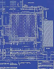
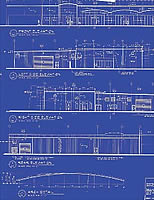
An understanding of the meaning of the various lines and symbols used on the drawings is essential to be able to “read” and make a “take-off” from the plans. The following explanation of some typical lines and symbols are keyed to Exhibit 1.
- Title block — gives the sheet number, a description of the drawing on that particular sheet, the name and location of the structure, the name of the architect or engineer, and the date of the drawings.
- Dimension lines showing the distance between two points.
- Main object lines, indicating visible outlines of objects, rooms, or buildings.
- Dashed lines indicating secondary or unseen objects.
- Extension lines, these lines extend beyond the main object lines and are used as an aid in showing dimensions.
- Scale Reference — this shows the scale that is used for a particular drawing.
- Building Section — also known as a “cross section”, is a view completely across the building or a section of the building. The arrows indicate the direction in which you would be looking.
- Wall Section Symbol — the top number of the section and the bottom number indicates the sheet on which the section will be found.
- Elevation Symbols — either exterior or interior, like the section symbol, the top number is the number of the elevation, and the bottom number indicates the sheet on which that elevation will be found. The arrow indicates the direction in which you would be looking.
- Structural Column Identification — the columns are usually marked with numbers on the long side and letters on the short side. These markings can sometimes be useful in orienting yourself to parts of the drawings.
- Circled Numbers — indicate doors and refer to the door schedule. Windows are usually identified by circled letters and refer to the window schedule. It should be noted that not all architects use this format, they might encase numbers or letters in squares or ovals.
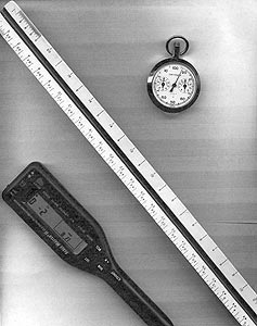
A building obviously cannot be drawn to full size, so a method has been devised to show a building or structure at a greatly reduced size. This technique is called drawing to scale. This simply means that every one foot of actual dimension is reduced to and drawn at a fraction of an inch, so that if the draftsman was using a 1⁄4" scale, each foot of actual dimension would be shown as 1⁄4" on the drawings. Principal drawings such as floor plans or elevations are usually drawn to a smaller scale than sections or details.
Several devices have been developed to allow us to “scale” the drawings and thereby convert the scaled drawings back to actual dimensions for our “take-off.” Exhibit 2 shows several of the more commonly used devices.
Architects usually have a caveat somewhere on their drawings about not scaling the drawings but rather to use the dimensions shown. That is well and good, but there are two problems, one is that process is time consuming, and very rarely sufficient dimensions given. So, for the most part we scale drawings. There are some concerns here though, one is that through the reproduction process, particularly when drawings are reduced, some distortion can occur that may affect the accuracy of your scaling. And it is not all that uncommon for the architect to put down the wrong scale, such as 1⁄8" when the drawing is actually 1⁄4". It is always good practice to check the dimensions before you start making a take-off.
Architectural drawings are divided into several different types of drawings and views, and it is important for the painting contractor to have a working knowledge of each and some insight as to how they relate to each other. The “view” or “cut” depicted by the drawing is important to the painting contractor, for only by understanding the depiction can an accurate take-off be made. Various plans and view will be discussed in this section.
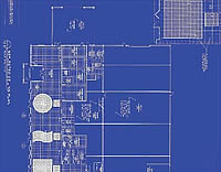
Site Plan (Exhibit 3)
This is a “plan” view drawing, which means you are looking down at whatever the architect is showing. The site plan shows the location of the building site, as well as roads, walkways, utilities, fencing, etc.. From this plan, the painting contractor might locate light poles, fencing, parking lot striping, bollards and other items that might require painting.
Floor Plan (Exhibit 1)
The floor plan is a plan view drawing, which means that we are looking down into the building with the roof off. This plan shows the layout of the walls and partitions, the location of doors, windows, stairs, cabinets, plumbing and similar items.
Exhibit 1 shows the dealership floor plan we are using. Typically the objects shown are dimensioned, overall building dimensions are given, together with the location of walls and partitions, doors, stairways and other details to be found in other drawings. In effect, since all of these key on the floor plan, the floor plans might well be called key sheets. It is from this plan, in conjunction with the finish schedule that the painting contractor gets his quantities of the different items of work he has to perform.
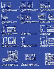
Interior Elevations (Exhibit 4)
Elevation drawings, either interior or exterior, are drawings of horizontal “head-on” views of a building or wall in a single plane. More simply, an elevation drawing depicts what you would see if you were standing directly in front of the wall.
Interior elevations are normally drawn to show special conditions or features that occur on a specific wall. For example, elevation 8-A4.3 shows a gypsum board soffit, and the location of cabinets, elevation 11-A.3 shows a painted wall and open shelving.
Building of Section
Drawings (Exhibit 5)
Building of Section drawings are sliced open views of an area to show construction arrangements which can’t be shown in plan or elevation drawings. Both large and small scale sections are needed throughout a set of drawings to adequately reflect the type of construction and materials to be used as well as other special construction features. Building sections 1 A3.1 and 2 A3.1 show that there are coffered ceilings in the sales area.
Wall Section Drawings (Exhibit 6)
The wall section drawing is essentially the same as that of the building section, except that it is usually restricted to a specific wall or part of a wall. The interior construction shown in these drawings are usually of no interest to the painting contractor, but other construction features may be. Section 1 A3.2 shows this wall has a light soffit, section 2 A3.2 shows a painted wood sill. The importance of these drawings, is that they may be the only place you will see these kinds of items.
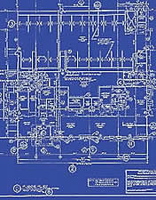
Reflected Ceiling Plans (Exhibit 7)
The reflected ceiling plan is a plan view drawing that shows the layout of the ceiling and various materials throughout the building. The reflected ceiling plan for the dealership shows the location of the coffered ceiling areas shown in the building section drawings, the location of some gypsum board ceilings, and also tells us that the exposed structure of the service are requires painting.
Exterior Elevations (Exhibit 8)
Like the interior elevations, exterior elevations are drawn just as if you were standing directly in front of and facing that particular wall. Two dimensions appear, length and height. To completely depict the exterior of a building, there should be a drawing for each elevation. The drawings are usually identified by compass direction — north elevation, south elevation, etc. Although some architects will use street names or in some cases, numbers.
Exhibit 8 shows us what is basically a metal building with EISF at the front and part of the sides. IT also shows us a metal ladder and overhead doors which require painting.
Schedules (Exhibit 9)
There are usually three different schedules provided by the architect somewhere in the drawings. There is the Schedule of Finishes, which provide a listing of the rooms or spaces in the building, and the various ceiling, wall and floor finishes. Some architects provide very detailed schedules, while others provide only basic information. There are the door and window schedules which provide a listing and description of the various doors and windows to be used in the building.
In each of these schedules, there is no standard format, architects basically use whatever they feel is adequate for any particular project.
Although this article does not specifically address the engineering drawings, the various types of drawings, plans, sections, etc. are similar and applicable to the engineering drawings as well as the architectural.